A couple of hours later, minus the electronics, now in a large heap on the garage floor
The old electronics . . .
Well, that was the easy bit. Now to get to grips with keyboard matrix scanning and digital interfacing via USB to a computer. I have in mind to implement this using
Arduino Uno
modules (£18.70 from Amazon), one
each for the two manuals and pedals, rather than simply buying in ready to run but more expensive purpose built electronic boards. These have sufficient digital I/O for
keyboard scanning, and also some analogue inputs for swell pedals. This console has two swell pedals which will conveniently match the swell and crescendo pedals of the
St. Anne's, Moseley virtual pipe organ that comes for free with Hauptwerk (actually the real organ only has a single swell pedal, the crescendo pedal is simulated in software).
A further Arduino module could be used to interface to the manual and pedal pistons and even to the draw stops. Implementation of pitch change in MIDI would also be very easy.
However the first target is simply to get a functional two manual and pedal organ for practice using the PC display for stop selection, and then build on that as the
whim takes me.
I will have to program the modules of course, using C/C++ in Arduino's integrated development environment, which I have not used before. Sadly there is no BASIC
implementation (Microsoft Visual Basic is my regular development language).
Manuals
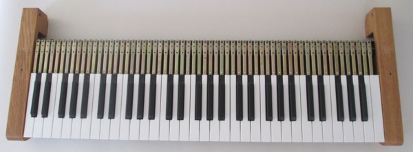
The unbranded manuals are built using 9.5" metal keys hinged at the rear, ensuring there is minimal variation from the horizontal when a key is depressed, a niggle with narrower
low cost keyboards. The keycaps are plastic. Overall the manuals have a good feel, although without the top resistance available in some expensive organ keyboards.
Underneath is a circuit board mounting open air contacts arranged electrically in the 8x8 diode matrix commonly employed for keyboard scanning. Each contact comprises a length
of spring that contacts a busbar when the key is pressed. Both springs and busbars are silver plated, and were in need of a good clean after several decades of use.
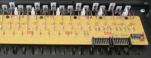
Although all the key contacts appeared to work reliably it made sense to clean them anyway. Fortunately the circuit board is readily removable from the keyboard chassis, permitting
easy access to the contacts for cleaning with silver polish. Three contacts and the adjacent busbar have been cleaned in the photo. Cotton wool bud sticks were helpful when cleaning
the springs. The springs themselves had to be well cleaned afterwards with a contact cleaner aerosol to remove the silver cleaner residue. Overall this was a fiddly business but
worth doing to give the keyboards a new lease of life.
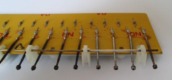
The way in which the contacts are arranged to implement an 8x8 row/column array can be seen here, the busbars forming the rows.
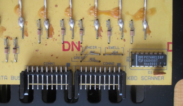
Electrical connection is made with a couple of ribbon cables. The integrated circuit is a 74138 TTL 3-to-8 way decoder, reducing the number of digital input lines required for row
selection from 8 to 3. Provision is made on the circuit board to identify the individual keyboard as great, swell or choir by wire links, two being snipped by the organ builder on
installation. It would of course be possible to use more than three of these keyboards with additional external selection.
Initially I MIDI-fied the keyboards with an Arduino Uno, one Arduino being more than fast enough for both, and pedals too. See circuit and code. However this required an external MIDI to USB cable and tied up two of the Arduino's digital lines
(A0, A1) for TX/RX, although only TX was used here.
I then discovered the Arduino Leonardo, a variant of the original Arduino Uno that allows the keyboard to appear at the USB port as a USB device without any programming required, while
not impeding the normal operation of the Atmel Studio compile/upload via the USB port, something that is not easily achievable with the Arduino Uno. The MIDIUSB library takes care of
the MIDI communication via the USB port. A single Arduino Leonardo was quite capable of scanning both manuals and the pedals with only an external 74138 decoder required to drive the
pedal diode matrix columns in the same way as implemented in the keyboards, due to the limited number of digital I/O lines available on the Arduino. See
code. However later I used two Arduino Leonardos, one for the two manuals
(see circuit), and another for the pedals, where the number of digital I/O lines were sufficient to
interface to the pedal column/row matrix directly.
Note that there is some contact debouncing inherent in the loop interval of the code execution, however no special attempt was made to implement more agressive debouncing since the
keyboard contacts were in good condition after cleaning, and the pedals use inherently trouble-free reed switches. See Hauptwerk Project 2 for the code to achieve more thorough
contact debouncing on an old Makin organ.
Pedals
The pedalboard is a standard RCO 32-note concave/radial specification.
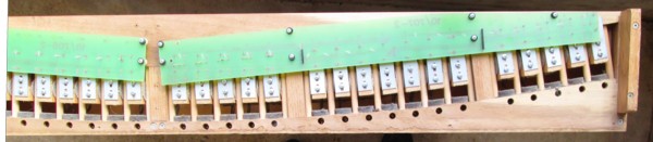
Electrical contact is by magnet and reed switch, with the magnets embedded in the pedalboard frame and the reed switches on a pair of circuit boards. Originally the switches were wired
into a separate diode matrix board which had been broken, and the two reed switch boards were modified by judicious track cutting to directly host the diodes and minimise external
wiring.
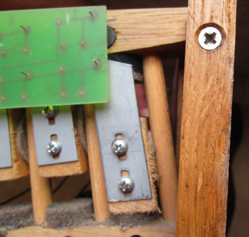
At rest each reed switch is shielded from the corresponding magnet's field by a metal strip attached to the end of the pedal. When a pedal is depressed the shield moves out of the way and
the reed switch is activated by the magnetic field. Slots in the shields allow vertical adjustment so that all the pedals sound at a uniform amount of travel (the RCO specification is half
way down).
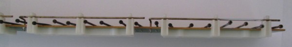
Drawstops
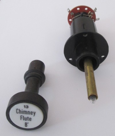
These are not strictly drawstops, since they do not stay drawn when pulled. Rather they are illuminated spring-loaded centre-off switches: pull to engage, push to disengage, either way
they return to the same position when released, the internal light providing the only indication of stop state. Made by Syndyne
they are no longer listed in their catalogue but are still used on new Rodgers organs. When reusing them it is a good idea to replace the 12 volt bulbs with modern bright white LEDs,
since the whole stop assembly will most likely have to be removed from the console to gain access to unsolder and dislodge a blown bulb (it is not just a screw in).
The stop knobs are in turned wood held in place with a small Allen screw. The stop engravings are on separate 1" diameter translucent plastic discs which can be easily popped out and
replaced or creatively re-used (for example the engraving ink can be dissolved out and new stop assignments made with 1" round laser labels).
These type of stops are useful in a budget electronic organ since the current required to light the bulb, and even less for LEDs, is a good deal less than that needed to power the
solenoids of conventional Kimber Allen style drawstops that typically draw 0.33A @ 24V (although the solenoids do not need to be continuously powered).
Swell Pedals
The organ came with a couple of plastic swell pedals. These work by shining the light from a LED through a plastic film whose aperture varies with pedal position and on to a light
dependent resistor. The aperture is crafted to simulate the opening of real swellbox shutters, where the first 10% of travel makes much more difference to the volume of sound than
the last 10%. Today one can implement this with a simple linear variable resistor in the swell pedal and software modelling to mimic the real swellbox characteristic.
The swell pedals were interfaced to analog ports on the Arduino Leonardo together with the four toe pistons. See circuit and code.
Thumb and Toe Pistons
The organ came with a strip of thumb pistons on the Great manual only. These are made by Syndyne and look unchanged in their
current catalogue. They contain tiny incandescent light bulbs and as with the drawstops it is a good idea to replace these with bright white LEDs before reuse.
The toe pistons are plastic bodied with brass toe caps. The caption has a small glass fuse style light bulb behind it which can be illuminated when the stop or coupler that the
piston controls is on. The bulb can be readily changed with the piston in place, although again it makes sense to substitute with a LED. The caption strip can easily be updated
with new lettering.
Installation
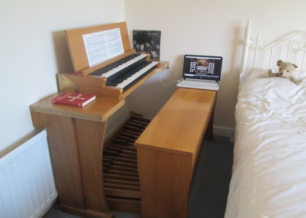
The organ has initially found a place in the corner of a bedroom as a barebones two manuals and pedals installation without any playing aids, where it is in regular use with
headphones as a practice instrument. The space taken up is surprisingly small, especially compared to the original console, the footprint being determined by the size of the
pedalboard. I will add swell pedals, drawstops and pistons in due course.
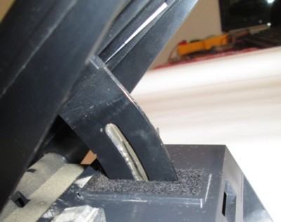
Music Desk Clips
The music desk on the Ahlborn console was not fitted with music clips. I bought a set of four (two are not enough for wide organ scores) from
ChurchOrganWorld. They make a big difference with organ music scores and
hymn books with stiff spines.
The recommended drill size is 3.5mm which may be appropriate for hardwood, however I suspected this would be a little loose in the softer MDF that the Ahlborn console
was made from, and a test hole in an inconspicuous location proved this. In fact 3.1mm holes gave just the right amount of pinch, allowing the clips to be moved
easily without flopping down. I chose the same spacing as the Makin console, 8.75 inches between the two inner clips and 6.5 inches between the inner and outer ones
either side.
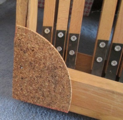
Pedal Board Thump
The console is installed in an upstairs bedroom and it was found that vigorous pedal playing generated obtrusive thumping through the floor to the lounge below. This was
cured by fitting quadrants of a 3/8 inch thick kitchen cork mat to each corner of the pedal board frame. This lifted the pedals off the floor and eliminated noise
transmission through the ceiling.
Pedal Board Warping
The pedal boards in many electronic organs are of fairly lightweight construction, and on the Ahlborn console the pedals themselves were made from 1 x 1 inch wood.
One of these had warped vertically, enough so that it became impossible to play notes either side without sounding that note too. Since planing the shaft would have
removed most of the wood it was decided to scrap the Ahlborn pedal board and for the time being use the one from the Makin console. This was made by a regular pipe
organ console builder and is of much sturdier construction, with 2 x 1 inch pedal shafts. Since the pedals are higher off the ground chrome legs were fitted to the
keyboard table to raise the manuals in relation to the pedals and restore the manual/pedals disposition to the standard RCO/AGO specification. It was necessary to
use the Makin organ bench too, with its adjustable height. The much greater bulk of the Makin pedal board frame ensures that there is no pedal thump to correct.
Thumb Pistons
The Ahlborn console had thirteen illuminated Syndyne thumb pistons on the great manual, of which several were broken, and none on the swell. For a while I
used the console without pistons, since even if repaired they were few in number and did not readily map to the Hauptwerk St. Anne or other organs in a way
that would have been useful as playing aids.
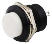
Sixteen thumb pistons on each manual would have been nice (and sixteen is a convenient hexadecimal number to interface digitally), but the cost of thirty two
genuine organ console pistons would have been considerable, and their depth would have precluded fitting them to the manual fronts. However I then discovered
some very low cost Chinese pushbutton switches that looked good as pistons and were shallow enough to fit in the space available behind the front plate below
the keys on each manual. A pack of fifty cost around £10 ($13) direct from China; they are available from local online resellers but at considerably greater
cost.
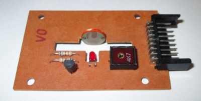
It was quick work with the Black & Decker and a hole cutter to make a series of additional 16mm holes in the sheet
metal piston rails and wire the switches up. These could have been arranged as a 4x8 diode matrix and scanned in the same way as the keyboards with a dedicated
Arduino board, however in the end the existing swell manual Arduino was used with a specially constructed interface board hosting four
CD4014 8-bit CMOS parallel to serial shift registers (see
circuit diagram,
board construction and
code). This requires just three unused I/O pins on the Arduino and a small amount of
additional code that does not affect the principal task of high speed keyboard matrix scanning.
New music clips and thumb pistons
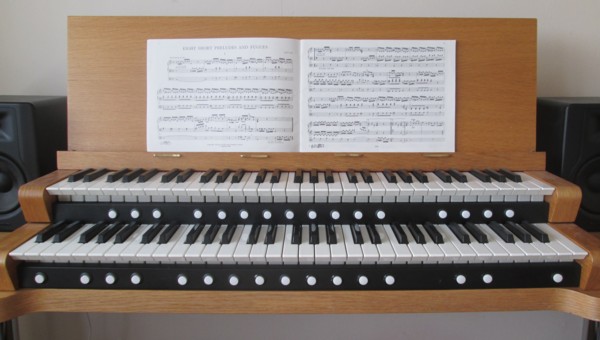
The number and positioning of the thumb pistons was chosen to suit the Hauptwerk St. Anne organ, but generally applicable to other organ sample sets. From left to right
on the Great: SET, SW-GT, SW-PED, GT-PED, Divisionals 1-9, Stepper - and +, GEN CANCEL. On the Swell: CR SW, CR GT, CR PED, Divisionals 1-9, Bass Coupler, SW-GT Melody,
PP, FF. The pistons are not engraved, but since the console is used with several Hauptwerk organs with different piston assignments one just has to remember their
assignments for each organ.
In Hauptwerk stop and piston input setup use Stop or Hold-piston: MIDI note-on/off. (Some organs need Momentary Piston: MIDI note-on to toggle the Sw-Gt,
Sw-Ped and Gt-Ped couplers).
The Bass Coupler and Melody Coupler are related. The Bass Coupler adds the selected pedal stops to the lowest note currently being played on the Great. It's a "cheater's
way" of achieving a full organ sound without use of the pedals. The Melody Coupler adds the selected Swell stops to the highest note being played on the Great, accentuating
the melody of the piece being played. This can be a good way to help the congregation hear the melody when they're singing an unfamiliar hymn, or to help add interest to
prelude or postlude music. On the St. Anne organ the Bass Coupler works up to F above middle C on the Great, while the Melody Coupler works on every note of the Great.
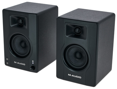
New Loudspeakers
The console was used first with headphones and then with domestic Hi-Fi equipment which was fine but did not really do justice to the lower pedal notes. Now
a pair of M-Audio BX5 D3 Active Studio Monitors are installed, around £92
each from Amazon. These are active units with their
own built-in amplifiers and just require an audio line input from the computer.
They are very compact speakers, but their frequency response at the low end reproduces 16' pedal stops well, right down to the lowest notes.
For true reproduction of 32' pedal stops something like the
Presonus Temblor T10 Active Studio Subwoofer, around £379 from
UK resellers, would do the job.
I subsequently bought a Behringer UCA202 USB audio interface, under £20 from
Amazon. This gives better audio performance than the typically cheap audio
I/O chip found on Windows PCs, and the 3.5mm audio jack on my laptop was becoming intermittent through repeated insertions. It works well with the M-Audio
speakers.
New Computer
A number of Windows computers have been used over the years. Hauptwerk version 4 worked well on a low cost Windows XP laptop with just 4Gb RAM back in 2012,
at least for the built-in St. Anne Moseley organ. More recently desktop (bought in 2013) and laptop (bought in 2015) computers with Intel i5 processor and
16Gb RAM have been used successfully with Hauptwerk version 5, the only limitation being the memory requirements of very large organ sample sets.
In April 2022 a Dell
Inspiron 27 7000 All-in-One Desktop was bought for dedicated use with Hauptwerk. This has the computer incorporated into the display case and wireless
keyboard and mouse, avoiding the tangle of cables in a traditional destop computer. With an Intel i5 processor, 8Gb RAM (now upgraded to the maximum 32Gb)
and a 500Gb solid state hard disk it can run larger organs on Hauptwerk version 7. Although this model has a standard screen touchscreen models are available.
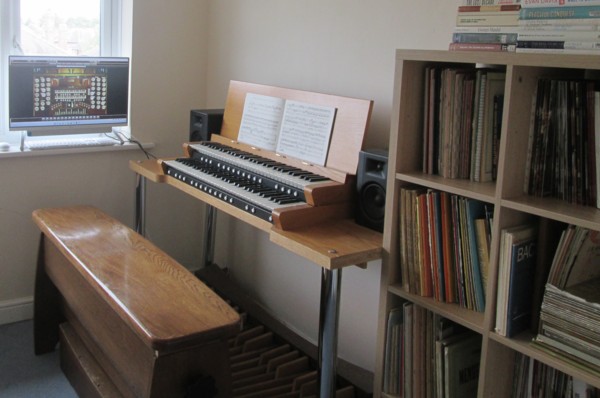
The revised arrangement of the console with new loudspeakers and computer
Swell Pedal
The swell pedals that came with the Ahlborn console were in poor condition and were replaced with a single new
Studiologic FP/50
organ-style expression pedal. This is supplied with a 2m long cable with a 1/4" TRS jack plug which was unnecessarily long and
bulky and was replace with a minature twin-core shielded cable terminating in a plug for direct connection to one of the analog
inputs together with +5V and ground of the Arduino that scans the manuals. The pedal contains a 10K linear potentiometer that
outputs a voltage between 0V and 5V depending on the position of the pedal and this is readily converted to MIDI signals in the
code.
2024: Upgraded Hauptwerk and New Organ Sample Set
Previously I was using Hauptwerk version 7 Lite, which only supports a single stereo channel output. Hauptwerk was upgraded to
version 8 Advanced edition, which supports many more features including multiple PC displays, multi-channel surround sound,
greater polyphony, more complex audio mixing and built-in convolution reverb.

Up to now I had been using either the St. Anne's Moseley organ that comes with Hauptwerk or a variety of free to use organ
sample sets from various sources. Now I have spent some serious money on a commercial sample set - the 1858 three manual
Walker organ at Romsey Abbey (NPOR), which has remainied
largely unaltered since it was first built apart from the addition of a new nave division, and one of the few large organs
in the U.K. still using Barker lever transmission. The
Romsey Abbey sample set was created by the organist Richard McVeigh.
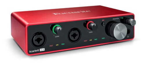
To take advantage of the multi-channel sound available in Hauptwerk version 8 and the Romsey Abbey and other sample sets
I acquired a Focusrite Scarlett 4i4
third generation USB Audio Interface which was, and still is, being sold at a discount following the release of the fourth
generation model. This enables four channels (i.e. two stereo pairs) of audio output from Hauptwerk for a modest price.
Other models offering six or more channels are available from Focusrite and other manufacturers but at considerably
greater cost.
For the third and fourth channels I chose the M-Audio BX3BT loudspeakers. These are smaller than the M-Audio BX5 D3 Active Studio Monitors
I already use but are very effective in a domestic setting.